230718 'HAND' http://farbe.li.tu-berlin.de/DEA_S.HTM or
http://color.li.tu-berlin.de/DEA_S.HTM.
For links to the chapter A
Colour Image Technology and Colour Management (2019), see
Content list of chapter A:
AEA_I in English or
AGA_I in German.
Summary of chapter A:
AEA_S in English or
AGA_S in German.
Example content part AEAI of some available parts AEAI to AEZI:
AEAI in English or
AGAI in German.
Example images part AEAS of all 26 parts AEAS to AEZS:
AEAS in English or
AGAS in German.
For links to the chapter B
Colour Vision and Colorimetry (2020), see
Content list of chapter B:
BEA_I in English or
BGA_I in German.
Summary of chapter B:
BEA_S in English or
BGA_S in German.
Example content part BEAI of some available parts BEAI to BEZI:
BEAI in English or
BGAI in German.
Example images part BEAS of all 26 parts BEAS to BEZS:
BEAS in English or
BGAS in German.
For links to the chapter C
Colour Spaces, Colour Differences, and Line Elements (2021), see
Content list of chapter C:
CEA_I in English or
CGA_I in German.
Summary of chapter C:
CEA_S in English or
CGA_S in German.
Example content part CEAI of some available parts CEAI to CEZI:
CEAI in English or
CGAI in German.
Example images part CEAS of all 26 parts CEAS to CEZS:
CEAS in English or
CGAS in German.
For links to the chapter D
Colour Appearance, Elementary Colours, and Metrics (2022), see
Content list of chapter D:
DEA_I in English or
DGA_I in German.
Summary of chapter D:
DEA_S in English or
DGA_S in German.
Example content part DEAI of some available parts DEAI to DEZI:
DEAI in English or
DGAI in German.
Example images part DEAS of all 26 parts DEAS to DEZS:
DEAS in English or
DGAS in German.
For links to the chapter E
Colour Metrics, Differences, and Appearance (2023),
under work, see
Content list of chapter E (links and file names use small letters):
eea_i in English or
ega_i in German.
Summary of chapter E:
eea_s in English or
ega_s in German.
Example content part eeaI of some available parts eeai to eezi:
eeai in English or
egai in German.
Example images part eeas of all 26 parts eeas to eezs:
eeas in English or
egas in German.
Project title: Colour and colour vision with Ostwald, device, and elementary colours -
Antagonistic colour-vision model TUBJND and properties for many applications
Chapter D: Colour Appearance, Elementary Colours, and Metrics (2022),
Main part DEA_S
Title: Ostwald colours as basis for the development of the human colour vision
1. Introduction and goals.
2. Antagonistic colour vision model.
3. Reflection of Ostwald colours and additive colour mixture.
4. Ostwald colours in colorimetric diagrams.
5. Reflection in the range 0,04 < R < 1,00 and normalised reflection R1=R/0,20.
6. Ostwald , sRGB and WCGa colours of different contrast in colorimetric
diagrams.
7. Antagonistic colour signals for Ostwald colours
of different contrast.
8. Properties of antagonistic optimal colours and signals for the definition of
colour-appearance attributes.
9. Colour vectors of the antagonistic colour vision model and relation with
linear colour values, and linear and nonlinear colour attributes.
10. Colour attributes Blackness N*, Whiteness W*, Chromaticness C*,
and the antagonistic colour attributes I*, T*, and A*
1. Introduction and Goals
This part shows connections between the
colour appearance, the elementary colours, and the colour metric.
Mathematical relations between the
colour appearance, the elementary colours, and the colour metric
shall be developed.
2. Antagonistic colour vision model
The term "antagonistic" of the Greek language is well known in medicine
for muscles. The muscles may work in "antagonistic" (or opponent) directions.
Colours may have "antagonistic" properties, which for example can be described by
"opponent", "complementary", "compensatory", "shadow effect", "after image effect",
"successive contrast", and "simultan contrast".
The "antagonistic" colour attributes can be described by
"lightness - darkness", "blackness - brilliantness", "whiteness - deepness",
"chromaticness - achromaticness".
These attributes change for example with the reflection of the ambient light
on the display, compare the properties for eight reflections:
OE73/OE73F1P0.PDF.
The question arises, if an "antagonistic" colorimetry is able to
describe many colour effects and colour attributes. These affects and attributes are applied
in the area of design, architecture, and art, and for example in the Swedish "Natural Colour System NCS".
3. Reflection of Ostwald colours and additive colour mixture
In many applications the question arrises, if these visual attributes can be calculated
from the CIE XYZ tristimulus values which are used in colorimetry.

Figure 2: Colour mixture of three basic colours to six colours (RYGCBM)d and White Wd.
For the download of this figure in the VG-PDF format, see
BEA70-7N.PDF.
The additive colour mixture of three Ostwald-optimal colours RGBd is shown.
The wavelength ranges are given by lines in the (x, y) chromaticity diagram.
The antagonistic colour pairs Rd - Cd, Yd - Bd, and Gd - Md mix to White Wd.
The index "d" is used for device.

Figure 3: Additive colour mixture of the three Ostwald colours
RGBd in colour image technology.
For the download of this figure in the VG-PDF format, see
BEA70-1N.PDF.

Figure 4: Additive colour mixture with displays in colour television
and in the colour-image technology.
For the download of this figure in the VG-PDF format, see
BEA71-5N.PDF.
4. Ostwald colours in colorimetric diagrams

Figure 5: Additive colour mixture of the Ostwald colours
in the CIE (x, y) chromaticity diagram.
For the download of this figure in the VG-PDF format, see
BEC50-1A.PDF.
Parameter is the tristimulus value Y and the colour name,
for example 94Yd.

Figure 6: Additive colour mixture of the Ostwald colours
in the colour image technology.
For the download of this figure in the VG-PDF format, see
BEH51-1A.PDF.
In the figures 2, 5, and 6 the same Ostwald colours are shown.
In the linear chromatic value diagram (A2, B2) the
Ostwald colours are located on a hexagon.
For example the antagonistic colours Red 38Rd and Cyan 62Cd
produce the White Wd by an additive colour mixture, compare Fig. 2.
Similar the antagonistic colours Yellow 94Yd and Blue 8Bd
produce the White Wd. For any antagonistic colour pair the additive
mixture of their tristimulus values Y produces always Y=100.
The radial chromatic values which are called CAB2, are approximately
constant in the chromatic value diagram (A2, B2). The
equations for the transformation from the CIE tristimulus values X, Y, Z
to the chromatic values A2, B2 and CAB2 are given in
the figure.

Figure 7: Additive colour mixture of Ostwald colours
in the (CAB2, Y) hue plane for the antagonistic pair Yd - Bd.
For the download of this figure in the VG-PDF format, see
BEF50-1A.PDF.
The partial mixture of Yellow 94Yd and Blue 6Bd produces a grey with
the tristimulus value Y=50.

Figure 8: Additive colour mixture of Ostwald colours
in the (CAB2, Y) hue plane for the antagonistic pair Rd - Cd.
For the download of this figure in the VG-PDF format, see
BEF51-1A.PDF.
The partial mixture of Red 38Rd and Cyan 62Cd produces a grey with
the tristimulus value Y=50. This is similar for the partial mixture
of Magenta 44Md and Green 56Gd.
The radial chromatic values which are called CAB2, are approximately
constant. For any antagonistic colour pair the additive mixture
of their tristimulus values Y produces always Y=100.
5. Reflection in the range 0,04 < R < 1,00 and normalised reflection R1=R/0,20

Figure 9: Colour mixture of three basic colours to six colours (RYGCBM)d and White Wd.
For the download of this figure in the VG-PDF format, see
BEE20-3N.PDF.
The additive colour mixture of three Ostwald-optimal colours RGBd is shown.
The antagonistic colour pairs Rd - Cd, Yd - Bd, and Gd - Md mix to White Wd.
Figure 9 shows the normalised refection factor
R1=R/0,2 between the R1-values
0,2 and 5. This corresponds to the reflection factors R=0,04 and R=1,00.
Figure 9 shows no change of the contrast C=25:1
compared to Figure 2. The minimum normalised reflection value is R1=0,2, and
the minimum reflection is R=0,04.
For matt surface colours the reflection factors are for black, mean grey and white
RN=0,036, RZ=0,18, and RW=0,90. In the figure these values are 10% larger.
Fig. 9 uses RN=0,04, RZ=0,20, and RW=1,00.
The very uneven spacing of R between RN=0,04, via RZ=0,20, up to RW=1,00
produces by the normalisation an equal spacing between
R1N=0,20, via R1Z=1,00, up to R1W=5,00 in Fig. 9.
The ordinate scale is a "geometric" scale. It is valid
R1W:R1Z = R1Z:R1N = 5. The contrast between white and black is
C = R1W:R1YZ = 25:1.

Figure 10: Additive colour mixture of three Ostwald colours RGBd
in the CIE (A2, B2) chromatic value diagram.
For the download of this figure in the VG-PDF format, see
BEH91-1A.PDF.
The figure shows the chromatic values for the high contrast
C=288:1 in dashed red and for the low contrast C=2:1 in green.
Both contrast steps are defined for office displays in ISO 9241-306. This ISO standard defines
for office displays the standard contrast C=36:1.
This corresponds to the tristmulus value YW=90 for White W
and YN=2,5 for a semi glossy colour Black N.
For a matt black with YN=4 the contrast is C=25:1.
6. Ostwald , sRGB and WCGa colours of different contrast in colorimetric
diagrams
In nature for surface colours the contrast between white and black can be
1000:1 on a sunny day, and only 2:1 on a foggy day. Only two contrasts C>288:1
and C=2:1 are used in the following figures

Figure 18: Additive colour mixture of Ostwald colours
in the (CAB2, Y) hue plane for the antagonistic pair Yd - Bd.
For the download of this figure in the VG-PDF format, see
BEN90-1A.PDF.
This figure shows the additive colour mixture for the antagonistic
Ostwald pair Yd - Bd
in the (CAB2, Y) hue plane. The antagonistic range Ya is used as the
ordinate. For the contrasts C>288:1 and C=2:1 the plots are normalised
to zero.
The plot is a schematic plot. In the figures 9, 32 and 35 a logarithmic
antagonistic function of Y is used. For the contrast range C=2:1
this logarithmic function is approximately proportional to the linear function of Y.
A linear relation is shown in Fig. 18 for both contrasts. With increasing contrast
compared to C=2:1 only a logarithmic ordinate seems appropriate.

Figure 19: Additive colour mixture of Ostwald colours
in the (CAB2, Y) hue plane for the antagonistic pair Rd - Cd.
For the download of this figure in the VG-PDF format, see
BEN91-1A.PDF.
This figure shows the hue plane Rd - Cd instead of Yd - Bd
in Fig. 18.

Figure 20: Additive colour mixture of sRGB-display colours
in the LAB2JND (A2, B2) chromatic value diagram for the three antagonistic pairs
Rd - Cd, Yd - Bd und Gd - Md.
For the download of this figure in the VG-PDF format, see
BEE31-8N.PDF.
The sRGB-display colours are located on an antisymmetric hexagon.
The antagonistic colours have in comparison to the zero point antagonistic
chromatic values. The additive mixtures leads therefore to white and the partial mixture
leads to grey. This antagonism is also valid for the
rgb*-chromatic values in the figure, compare for example rgb* = (1 0 0)
for Red Rd and rgb* = (0 1 1) for Cyan Cd.

Figure 21: Additive colour mixture of sRGB-display colours
in the CIELAB (a*, b*) chroma diagram for the three antagonistic pairs
Rd - Cd, Yd - Bd und Gd - Md.
For the download of this figure in the VG-PDF format, see
BEE31-2N.PDF.
The sRGB-display colours are NOT located on a antisymmetric hexagon.
The antagonistic colours have in comparison to the zero point NO antagonistic
chromatic values. However, as shown in Fig. 20, the partial mixture leads to grey.
The antagonism is valid for the rgb*-chromatic values in the figure, compare
for example rgb* = (1 0 0) for Red Rd and rgb* = (0 1 1) for Cyan Cd.

Figure 22: Additive colour mixture of sRGB-display colours and Ostwald
colours
in the (A2, B2) chromatic value diagram for the three antagonistic pairs
Rd - Cd, Yd - Bd und Gd - Md.
For the download of this figure in the VG-PDF format, see
BEU00-2N.PDF.
The sRGB-display colours and the Ostwald colours are located on a triangle.
The additive mixture of the antagonistic colours produces white. The antagonism is also valid
for the XYZ tristimulus values in the table of the figure, compare for example
YR=38 for Red Rd and YC=62 for Cyan Cd. It is valid
YR + YC = YW = 100.

Figure 23: Additive colour mixture of WCGa-display colours
in the LAB2JND (A2, B2) chromatic value diagram for the three antagonistic pairs
Rd - Cd, Yd - Bd und Gd - Md.
For the download of this figure in the VG-PDF format, see
BEE41-8N.PDF.
The WCGa-display colours are located on a antisymmetric hexagon.
The antagonistic colours have in comparison to the zero point antagonistic
chromatic values. The additive mixture leads therefore to white and the partial mixture
leads to grey. This antagonism is also valid for the
rgb*-chromatic values in the figure, compare for example rgb* = (1 0 0)
for Red Rd and rgb* = (0 1 1) for Cyan Cd.

Figure 24: Additive colour mixture of WCGa-display colours
in the CIELAB (a*, b*) chroma diagram for the three antagonistic pairs
Rd - Cd, Yd - Bd und Gd - Md.
For the download of this figure in the VG-PDF format, see
BEE41-2N.PDF.
The WCGa-display colours are NOT located on a antisymmetric hexagon.
The antagonistic colours have in comparison to the zero point NO antagonistic
chromatic values. However, as shown in Fig. 20, the partial mixture leads to grey.
The antagonism is valid for the rgb*-chromatic values in the figure, compare
for example rgb* = (1 0 0) for Red Rd and rgb* = (0 1 1) for Cyan Cd.

Figure 25: Additive colour mixture of Ostw-display colours
in the LAB2JND (A2, B2) chromatic value diagram for the three antagonistic pairs
Rd - Cd, Yd - Bd und Gd - Md.
For the download of this figure in the VG-PDF format, see
BEE61-8N.PDF.
The Ostwald colours are located on a antisymmetric hexagon.
The antagonistic colours have in comparison to the zero point antagonistic
chromatic values. The additive mixtures leads therefore to white and the partial mixture
leads to grey. This antagonism is also valid for the
rgb*-chromatic values in the figure, compare for example rgb* = (1 0 0)
for Red Rd and rgb* = (0 1 1) for Cyan Cd.

Figure 26: Additive colour mixture of Ostw-display colours
in the CIELAB (a*, b*) chroma diagram for the three antagonistic pairs
Rd - Cd, Yd - Bd und Gd - Md.
For the download of this figure in the VG-PDF format, see
BEE61-2N.PDF.
The Ostw colours are NOT located on a antisymmetric hexagon in the CIELAB (a*, b*)
chroma diagram. The antagonistic colours have in comparison to the zero point NO antagonistic
chromatic values. However, as shown in Fig. 20, the partial mixture leads to grey.
The antagonism is valid for the rgb*-chromatic values in the figure, compare
for example rgb* = (1 0 0) for Red Rd and rgb* = (0 1 1) for Cyan Cd.
The following two figures show the Ostwald, sRGB, and WCGa colours
all together in the CIE chromaticity diagram (x, y)
and the chromatic value diagram (A2, B2) of LAB2JND.

Figure 27: Additive colour mixture of Ostw, sRGB, and WCGa display colours
in the CIE-chromaticity diagram (x, y) for the three antagonistic pairs
Rd - Cd, Yd - Bd und Gd - Md.
For the download of this figure in the VG-PDF format, see
BEU00-8N.PDF.
The Ostw, sRGB, and WCGa colour-hue circles are located on three
triangles. They are marked by red, green and blue colours.
In addition a special Ostwald colour of a colour half with the
wavelength limits 472 nm and 572 nm is shown. This colour pair is called
G2 - M2.

Figure 28: Additive colour mixture of Ostw, sRGB, and WCGa display colours
in the LAB2JND (A2, B2) chromatic value diagram for the three antagonistic pairs
Rd - Cd, Yd - Bd und Gd - Md.
For the download of this figure in the VG-PDF format, see
BEU01-8N.PDF.
The Ostw, sRGB, and WCGa hue circles are located on three hexagons.
They are marked by red, green and blue colours.
The hexagon of the WCGa colours in blue is larger in the red-green
direction compared to the hexagon of the Ostw colours.
This increases the WCGa-colour gamut compared to
the Ostw-colour gamut.
Summary of this part
The Ostwald, sRGB, and WCGa colours were shown separately for the two
contrast steps C>288:1 and C=2:1. The chromatic value diagrams (A2, B2)
of LAB2JND and the chroma diagrams (a*, b*) of CIELAB serve for the presentation.
The colour space LAB2JND includes the antagonistic properties of the three
antagonistic colour pairs. The colour space CIELAB fails in this point.
The colour gamut enhancement is in the CIELAB-chroma diagrams
(a*, b*) larger compared to the LAB2JND-chromatic value diagrams (A2, B2).
More research seems necessary to evaluate these two different results.
7. Antagonistic colour signals for Ostwald colours
of different contrast
This section tries to show the relation between colorimetric and
physiological results.

Figure 29: Antagonistic signals for the green Ostwald colour G
For the download of this figure in the VG-PDF format, see
BEE91-3A.PDF.
The first two arrows show the reflection factor of two green colours Gn and G.
A blackish green Gn is located in the middle between Black N
and the green Ostwald colour G.
The next two arrows show the reflection factor of two green colours Gw and G.
A whitish (w) green Gw is located in the middle between White W and the
green Ostwald colour G.
The figure ordinate uses the coordinate R2=log[R/0,2].
This coordinate R2 is intended to be proportional to the
triangle lightness t*. For the contrast ratio C=8:1
the triangle lightness t* is given. In the figure the value
of t* is equal to the CIELAB lightness L*.
In the CIE colorimetry the CIELAB lightness L* is different for the green
Ostwald colour G and different for all other chromatic
Ostwald colours.
The three reflection factors R=0,071, 0,200, and 0,564
correspond to the three CIE tristimulus values Y=7,1, 20,0 and 56,4.
According to the CIELAB lightness formula
L* = 116 (Y/100) ^ (1/3) - 16
the three CIELAB lightness values are L*=32,03, 51,84, and 79,84.

Figure 30: Antagonistic signals for the magenta-red Ostwald colour
M
For the download of this figure in the VG-PDF format, see
BEE91-6A.PDF.
The first two arrows show now the reflection factor of two
magenta-red colours Mn and M, and the next two the magenta-red colours
Mw and M.
A blackish magenta-red Mn is located in the middle between Black N and the
magenta-red Ostwald colour M. Similar a whitish magenta-red Mw
is located in the middle between White W and the magenta-red
Ostwald colour M.

Figure 31: Relation between reflection, log[reflection],
and triangle lightness t*
For the download of this figure in the VG-PDF format, see
BEE91-8A.PDF.
The figure shows three different reflections R, R1,
and R2. The calculation of the contrast C is given.

Figure 32: Antagonistic signals for eight chromatic
Ostwald colours and white for the contrast C=8:1.
For the download of this figure in the VG-PDF format, see
BES81-7N.PDF.
For the description compare the text for the figures 21 to 23.
The six Ostwald-optimal colours of Figure 32 define
the Ostwald-hue circle. Figure 28 compares the Ostwald, sRGB, and WCGa
hue circles in the chromatic value diagram (A2, B2).
The colorimetric chromatic values A2 and B2 of the
Ostwald-hue circle are approximately on a circle.
All antagonistic colours have equal absolute chromatic values
|A2| and |B2|.
The circle diameter reduces for the two contrasts C>288:1 (black lines)
and C=2:1 (chromatic lines) by a factor two.
In the colour spaces LABJND, LAB1JND, and LAB2JND this is similar
for the three devices:
sRGB, see
BEE3L0NP.PDF,
WCGa, see
BEE4L0NP.PDF,
and Ostw, see
BEE6L0NP.PDF.
In the chromatic value diagram (A2, B2) of LAB2JND and
in the chroma diagram (a*, b*) of CIELAB
the following colours are compared:
1. the sRGB colours in Fig. 20 and 21, and
2. the WCGa colours in Fig. 23 and 24, and
3. the Ostw colours in Fig. 25 and 26.
Because all antagonistic RGB, WCGa and Ostw colours mix
to the achromatic White; W, equal absolute chroma values
|a*| und |b*| are expected.
For the three devices sRGB, WCGa and Ostw the CIELAB-chroma values C*ab
are often different by a factor two. Therefore the CIELAB-colour space
includes NOT the expected visual properties.
This is a difficulty of the present CIE colorimetry for may applications
in the area of colour appearance, and of design, and in architecture and in art.
In addition the different colour difference formulae, for example
CMC, CIE94, and CIEDE2000 include transformations of the unwanted visual
properties of the CIELAB data. This is similar for the colour appearance models
CIECAM02 and CIECAM16 (2021 under vote).
Summary of this part
In the LAB2JND colour space the colorimetric chromatic values A2 and B2
of the Ostwald-hue circle are approximately on a circle.
All antagonistic colours have equal absolute chromatic values
|A2|, |B2|, and |CAB2|.
In the CIELAB colour space the colorimetric chroma data a* and b* of the
Ostwald-hue circle are often by a factor two different.
All antagonistic colours have NOT equal chroma values
|a*|, |b*|, and |C*ab|.
Therefore improved colour difference formulae and colour
appearance models for many applications are possible with LAB2JND.
The antagonistic colour vision model seems to include many advantages for
many applications in the area of colour appearance, in the design, in the architectur
and the art.
8. Properties of antagonistic optimal colours and signals for the definition of
colour-appearance attributes
An Optimal colour is usually defined by two jumps of the reflection curves.
With a special band width and with compensatory wavelength limits
surface colours are produced with the maximal chromatic values CAB2.
They are called Ostwald-optimal colours.
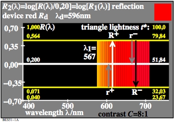
Figure 33: Spectral reflection of the Ostwald-optimal colour Red Rd
For the download of this figure in the VG-PDF format, see
BES51-1A.PDF.
The two spectral colours of the wavelength 567 nm and of the wavelength 380 nm
are compensatory or complementary. With an appropriate ratio the colours of the
two wavelength mix to the White W of the CIE-standard illuminant D65 (daylight).
The arrows from down to top shall indicate, that one can mix colours
additive, if one starts with black.
The arrows from top to down shall indicate, that one can mix colours
subtractive, if one starts with white.
The importance of the arrows will be further described in Fig. 35 and 36.
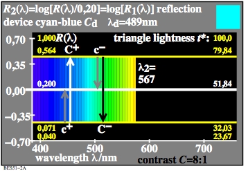
Figure 34: Spectral reflection of the Ostwald-optimal colour Cyan Cd
For the download of this figure in the VG-PDF format, see
BES51-2A.PDF.
The additive mixture of the colours Cyan Cd and Red Rd produces white.
The additive mixture produces the total spectrum of White W.
The two colours Cd and Rd consist of spectral colours in different ranges.
Their appearance is shown on the right top in a colour square.
On nearly all displays the white is mixed by the device colours
Red Rd and Cyan Cd. Cyan Cd is a mixture of Green Gd and Blue Bd.
White W is therefore mixed by the three colours Rd, Gd, and Bd.
Summary of this part
Antagonistic Ostwald-optimal colours and device colours mix two the
white of the standard illuminant D65. The colour mixture can start from Black N
or from White W.
9. Colour vectors of the antagonistic colour vision model and relation with
linear colour values, and linear and nonlinear colour attributes
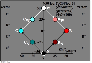
Figure 35: Colour mixture of Red and Cyan with start
by either Black N or White W
For the download of this figure in the VG-PDF format, see
BES80-2A.PDF.
The blackish vectors (arrows) from down to top shall indicate:
For the start from black one can mix the dark red colour RN with r+ and
and the lighter most chromatic colour Red R with R+ of Fig. 33.
Similar one can subtract from the whole spectrum White W the colour Red R
and produces the colour Cyan C.
The white vectors (arrows) from top to down shall indicate:
For the start from white one can mix
the light colour CW with r- and
the darker most chromatic colour Cyan C with R-.
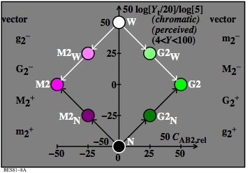
Figure 36: Colour mixture of Green G2 and Magenta M2 with start
by either Black N or White W
For the download of this figure in the VG-PDF format, see
BES80-8A.PDF.
The blackish vectors (arrows) from down to top shall indicate,
that for the start from Black N one can mix
the dark green colour G2N with g2+ and
and the lighter most chromatic colour Green G2 with G2+ of Fig. 32.
Similar one can subtract from the whole spectrum White W the colour Green G2
and produce the colour Magenta M2.
The whitish vectors (arrows) from top to down shall indicate,
that for the start from white one can mix
the light colour M2W with g2- and
and the darker most chromatic colour Magenta M2 with G2-.
The vectors with a "+" or "-" correspond to physiological
signals in the retina. There are probably eight signal processes
W-N, R-C, Y-B, and G-M and the antagonistic processes
N-W, C-R, B-Y, and M-G. Often only
six signal processes W-N, Y-B, and R-G and the antagonistic processes
N-W, B-Y, and G-R are described.
The signals R-G are probably created as the mean of R-C and M-G.
The antagonistic signals G-R are probably created as the mean of
C-R and R-M. This mixture may happen in the retina or in a
higher signal step of colour vision.
Summary of this part
Antagonistic colour vectors of a device mix to the White W of the
standard illuminant D65. The colour mixture can start from Black N
or from White W. With vectors the colours of the antagonistic hues
can be produced from White W and Black N.
10. Colour attributes Blackness N*, Whiteness W*,
Chromaticness C*, and the antagonistic colour attributes
I*, T*, and A*
The visual system can order the colours by colour attributes.
For the determination and differentiation one needs defined criteria.
For the antagonistic pair blackness N* and Brilliantness I*
this is the criteria neither blackish nor luminous.
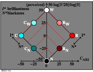
Figure 37: Colour attribute blackness N* and brilliantness
I*
For the download of this figure in the VG-PDF format, see
BES21-6A.PDF.
Dashed red lines show four colour series. Each colour series has the equal
colour attribute blackness N* or the antagonistic equal colour attribute brilliantness
I*.
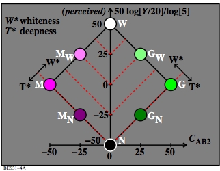
Figure 38: Colour attribute whiteness W* and deepness T*
For the download of this figure in the VG-PDF format, see
BES31-4A.PDF.
Dashed red lines show the equality of the colour attributes
whiteness W* or of the antagonistic colour attribute
deepness T*.
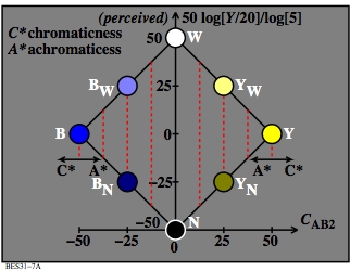
Figure 39: Colour attribute chromaticness C* and
achromaticness A*
For the download of this figure in the VG-PDF format, see
BES31-7A.PDF.
Dashed red lines show the equality of the colour attribute
chromaticness C* or of the antagonistic colour attribute
achromaticness A*.
Summary of this part
Colour vectors which start from Black N define the antagonistic
colour attributes blackness N* and brilliantness I*.
Colour vectors which start from White W define the antagonistic
colour attributes whiteness W* and colour deepness T*.
Equal colour vectors of antagonistic colour pairs define the
antagonistic colour attributes chromaticness C* and
achromaticness A*.
This web page is since 2021 under work.
In future the figures and the text may be improved.
-------
For the TUB start site (not archive), see
index.html in English, or
indexDE.html in German.
For the TUB archive site (2000-2009) of the BAM server
"www.ps.bam.de" (2000-2018)
about colour test charts, colorimetric calculations, standards,
and publications, see
indexAE.html in English,
indexAG.html in German.
For similar Information of the BAM server "www.ps.bam.de"
from the WBM server (WayBackMachine)
https://web.archive.org/web/20090402212108/http://www.ps.bam.de/index.html


